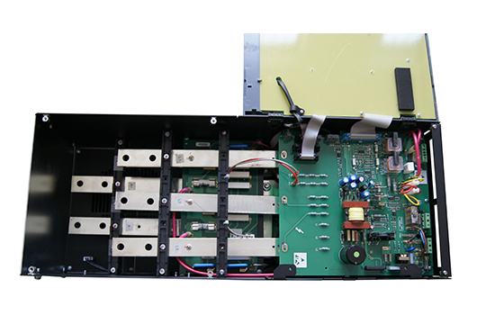
Common detection methods for DC Drive maintenance:
1) The output speed is the highest, not adjustable, and the rectifier voltage of P4 is 200V.
A. Connect the device to the 220V/220V isolation maintenance power supply, disconnect the V1 gate resistance from the circuit, that is, disconnect the V1 triggering current path, and measure that the P4 rectification voltage is still 200V, then the main circuit thyristor V breaks down and short-circuits.
b. Given speed circuit W2 performance deteriorates, the resistance value of movable arm and upper fixed end increases, so that the regulating voltage cannot increase, and the maximum speed signal is mistakenly given.
2) FUSE fuse fuse. Check whether any of the four diodes in the bridge rectifier circuit P4 have been short-circuited.
At the same time, it is necessary to check the protection circuit W1, N3, N4 circuit and other faults, so that the protection failure, so that P4 burned.
3) The output voltage is zero. Involved in three aspects of the circuit, one main circuit damage, such as thyristor V1, current sampling resistance R3 open circuit damage; Second, to protect the circuit misaction, forced phase shift triggers the circuit to stop working; Three is the fault of the phase trigger circuit itself, can not output normal phase shift trigger pulse signal.
a. Check that there is no circuit break fault in R3, short connect the T1 and T2 poles of thyristor V1, and test whether the output end of P4 rectifier has 200V voltage. If there is still no normal DC voltage output, P4 is damaged (load resistance is connected to make the test easy to judge). If there is normal voltage output, continue the next step of inspection;
b. Short connect the C and E ejectors of pulse amplifier tube V2 with wires or tweezers, and manually switch on the triggering current path of V1. The output voltage of P4 is still 0, indicating that the thyr V1 is damaged; Test P4 can output 200V DC voltage, indicating that the main circuit is intact; Proceed to the next step;
c. Before checking the phase shift trigger circuit, the protection circuit should be ruled out whether the wrong action, so that the phase shift trigger circuit can not be put into normal operation. If the fault indicator D4 is always on, it indicates that the overcurrent protection circuit is in the misoperation state. Check the two-level protection circuit N3 and N3. If D4 is not bright and the Uce of V6 is less than 1V, it is the breakdown damage of V6.
The more effective inspection method is to remove the emitter of V from the circuit board, adjust W2, and measure the normal change of P4 output voltage. The fault is the protection circuit false start control; P4 still has no output, the fault is in the normal phase trigger circuit, continue to the next step of inspection;
D, adjust the W2, N2 1 foot about whether there is a corresponding 0 to 8 v dc voltage output, if the change is normal, the N2 at the corresponding level and the level before the phase-shift circuit works well, failure in C5, V2 touch power amplifier stage, such as V2 magnification become low, or open circuit, capacitor C5 capacity decline or loss of capacity, causing trigger current is too small, V1 can't normal open, etc.; If pin 1 of N2 has a fixed positive voltage above 8V or is 0V, the fault is in N2 and the preceding circuit. Should continue the next check;
e. According to the circuit analysis, judge the waveform of each point, and then estimate or calculate the voltage value of each key point of the phase-shifting trigger circuit, make fault diagnosis, and then complete the repair of the DC Drive.

 Chinese
 English

 SERVICE HOTLINE